🎯 Goal and finished result
In this Hands-on ①, we'll build the simplest possible map from start to finish: a station on a single track (one line) where two trains pass each other. It's that classic scene you see on rural single tracks—an up train and a down train meet at a station and swap places.
What you'll learn in this tutorial
- How to create a new map and scenario, and how to work through the editing flow (Company → Wiring → Equipment → Operations)
- How to draw a station with facing (opposed) platforms (two platforms, two tracks)
- Setting track circuit lengths and speed limits
- The basics of levers, routes, signals, and departure buttons
- Path groups and registering trains, all the way to showing the diagram
✏️ Draw a plan first (the most important step)
Before you touch the editor, we strongly recommend sketching a simple plan on paper. If you just start building, you tend to hit rework later: "the track circuit is too short to place a lever," or "I set things up in the wrong order and have to redo it." If you decide the positions of tracks, the station, and levers on paper first, the work goes straight through without backtracking.
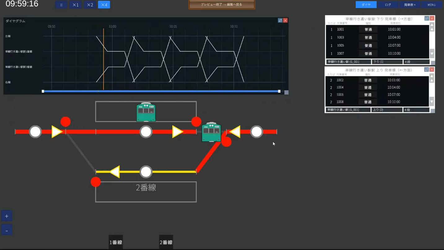
The station we'll build this time looks like this. This is the map for the whole tutorial.
🏢 STEP 1 Company (classes and types)
The menu at the top left runs File → Company → Wiring → Equipment → Operations. Working through it in that order, left to right, minimizes rework. Let's start with Company.
1-1. Create a new map
- File → New Map. Enter a map name and click Create (it doesn't have to be a real station name; here we use
Passing) - Next you'll be asked to create a scenario. A scenario is the mechanism that lets one map hold multiple time periods—morning, daytime, night, and so on. If you have no preference, leave it at the default (DayTime), or use something clear like
Daytime
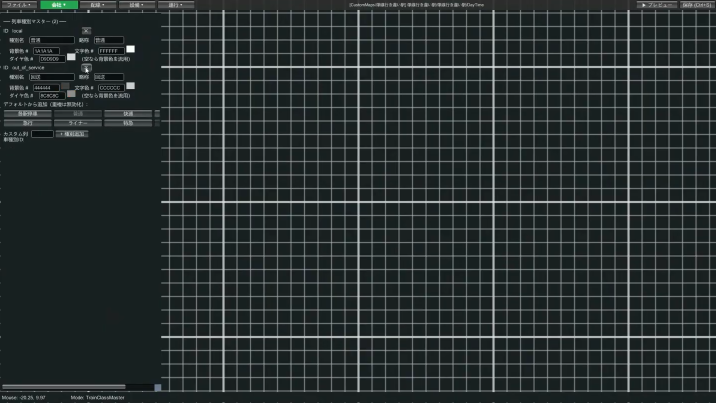
1-2. Trim the train classes down to "just what you use"
Company → Train Classes. Eight classes are provided by default, but the trick is to keep only the ones this map uses and delete the rest. Our small single-track station only expects local trains to stop, so we keep just two: "Local", plus "Out of Service" for non-revenue trains.
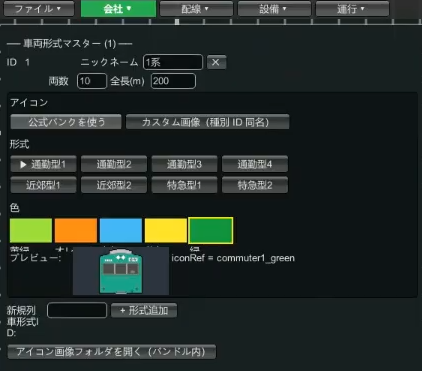
1-3. Create one train type (rolling stock)
In Company → Train Types, define one set of rolling stock to run.
- Enter the train type ID (e.g.
1) and a nickname (e.g.Series 1) - Enter the number of cars (e.g. 10 cars) and the total length (e.g. 200m; 10 cars is roughly 200m)
- For the icon, choose "Use official bank" → pick a commuter type or similar, and a color you like (e.g. green)
- Save
→ For more, see the Company editing guide
🛤 STEP 2 Wiring (tracks and station)
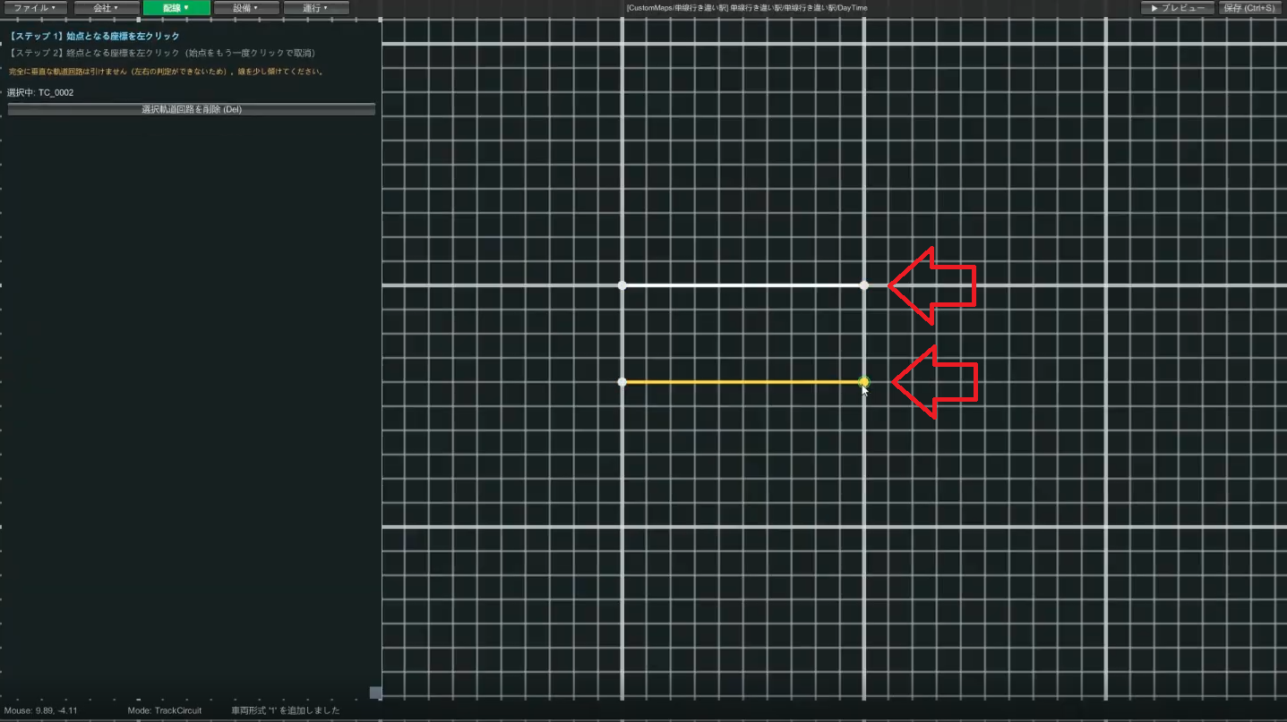
2-1. Draw the station's Track 1 and Track 2 (facing platforms)
Wiring → Track Circuit. Click a start point → click an end point to draw one segment. First draw Track 1, then Track 2 a little below it. Leave at least about 4 cells of gap between the two tracks (if they're too close, placing platforms and buttons later becomes awkward).
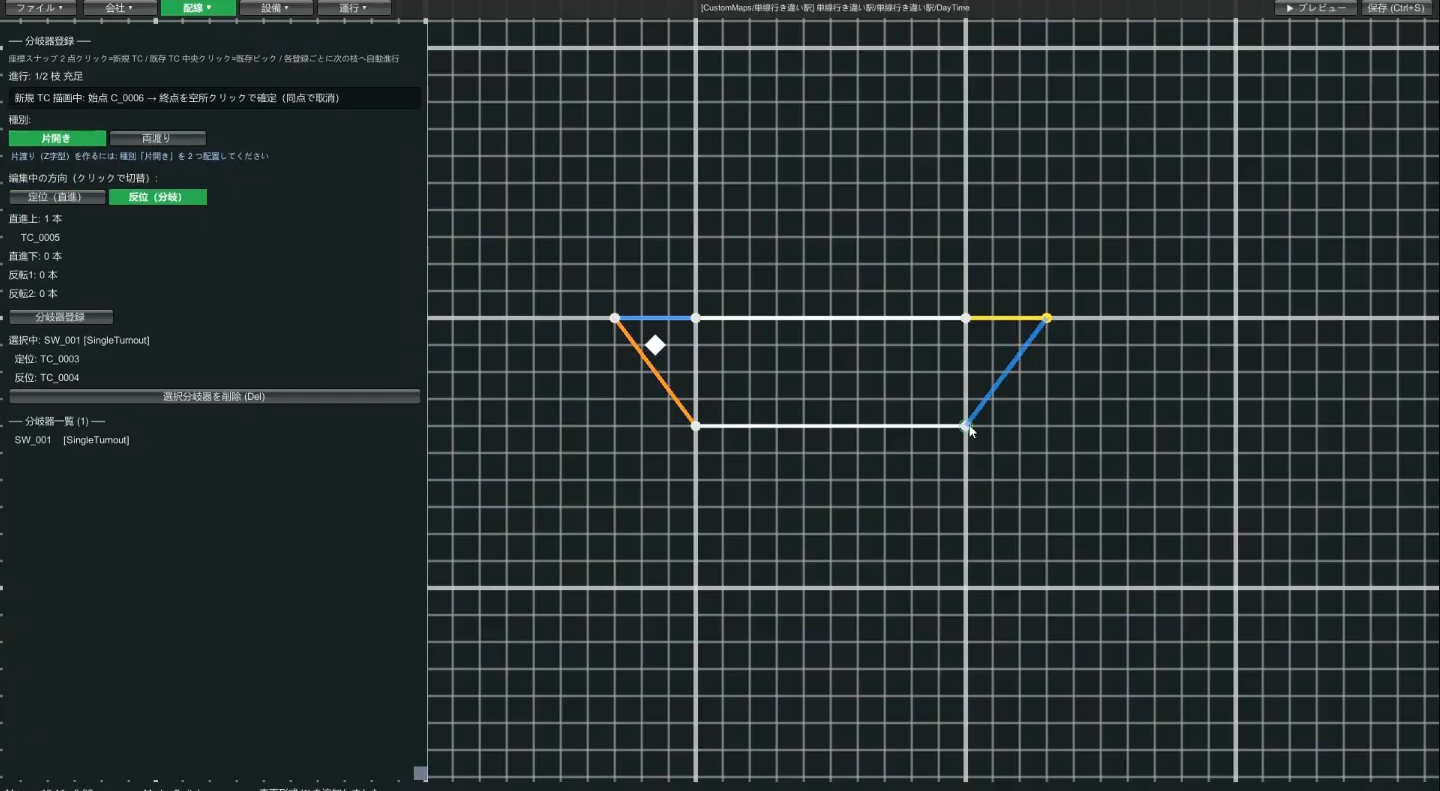
2-2. Place switches on both sides of the station
Wiring → Switch. Use the single switch type. Connect from the straight direction first, then create one switch at each end of the station that splits into Track 1 and Track 2, and save.
2-3. Draw the track circuits outside the station (single-track sections)
Draw the single-track section track circuits, one to the left and one to the right—that is, outside the switches, extending out from each side of the station. On a real railway there are multiple track circuits between stations, but here we use one each for clarity.
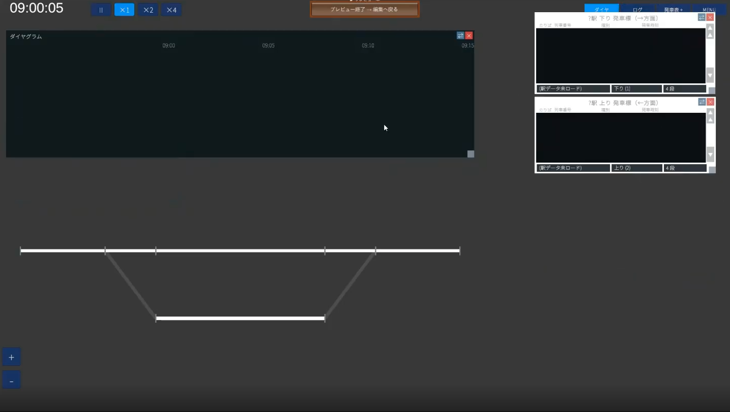
Once you've gotten this far, run ▶ Preview once to check the track is drawn correctly. Previewing frequently is the trick to catching mistakes early.
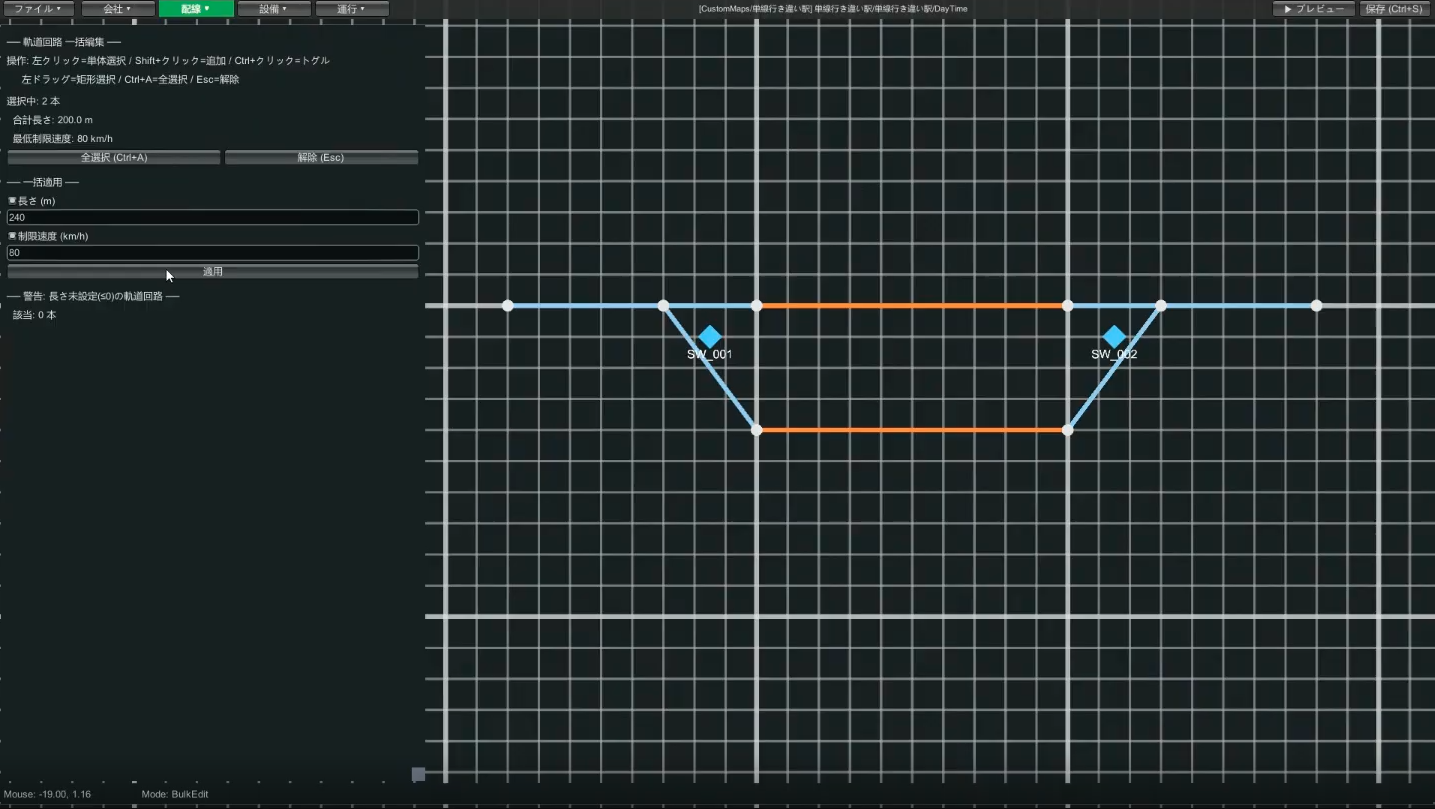
2-4. Set track circuit lengths and speed limits (bulk edit)
In Wiring → Bulk Edit mode, set the length and speed limit of track circuits all at once. If you leave the default length (such as 100m), a 200m train will stick out of the station, so set these properly here.
| Location | Guideline length | Guideline speed limit |
|---|---|---|
| Station Track 1 / Track 2 | 240m (200m train + 20m front and back) | 80km/h |
| Switch (straight side) | Short, e.g. 40m | 80km/h |
| Switch (diverging side) | Short, e.g. 40m | 40–45km/h (slow) |
| Single-track sections outside the station | Long, e.g. 600m | 80km/h |
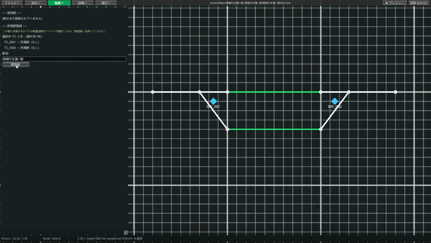
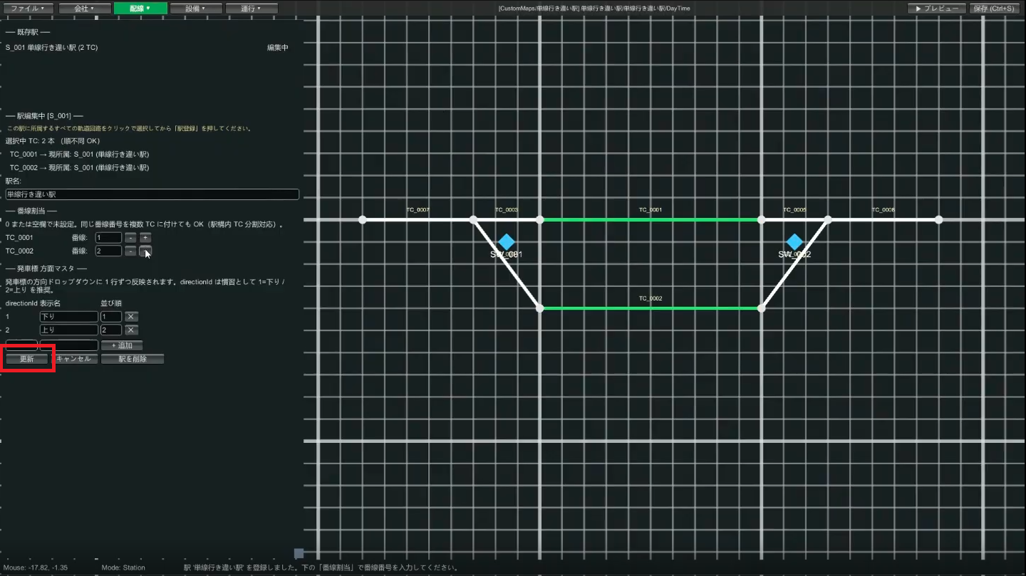
2-5. Register the station and assign track numbers
- In Wiring → Station, select the platform track circuits where trains stop (Track 1 and Track 2)
- Enter a station name (e.g.
Passing Station) and register - Track number assignment appears: set the upper track circuit (e.g.
TC001) as Track 1, the lower one (TC002) as Track 2, and press Update
2-6. Place the platforms
Wiring → Platform. Draw a platform by clicking its four corners to make a rectangle. Since these are facing platforms, place a platform on the upper side of Track 1's track circuit and on the lower side of Track 2's track circuit.
Each platform lets you write a track number on its top and bottom edges. For example, Track 1's platform is above the track circuit, so enter "Track 1" on the platform's lower side (think of it as the track number facing the track side).
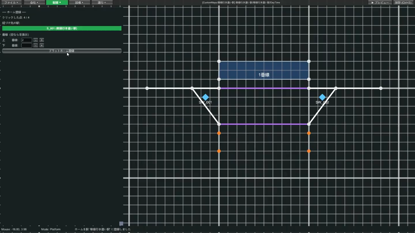
Place Track 2's platform the same way, then check the look in ▶ Preview and save with Ctrl+S.
→ For more, see the Wiring editing guide
🚦 STEP 3 Equipment (levers, routes, signals, departure buttons)
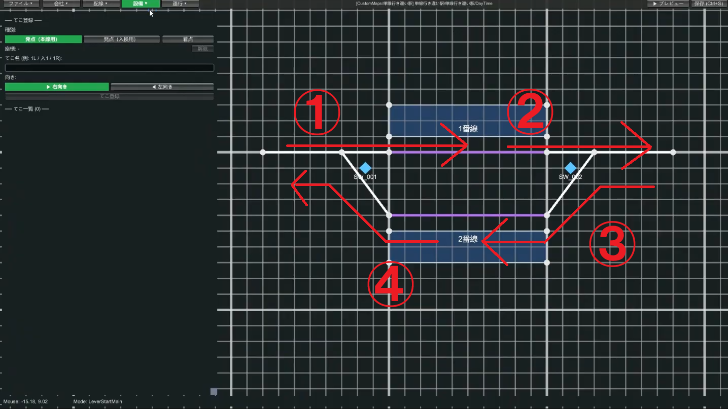
3-1. Think about "routes" first
Before placing levers, think about what routes (the paths trains travel) you need. This station needs the following four.
- A route into Track 1 / a route out of Track 1
- A route into Track 2 / a route out of Track 2
A route is made from a pair of a "start lever (departure side)" and an "end lever (destination side)", so we'll place the levers for these four routes.
1, 2, left-bound as 11, 12—keeps things organized.
3-2. Place the levers
Equipment → Lever. Start levers come in "Main Start" and "Shunt Start" varieties, but just Main Start is fine at first. Since we decided right-bound = Track 1 and left-bound = Track 2 this time, place them as follows.
| Route | Start lever (number) | End lever (letter) |
|---|---|---|
| Into Track 1 | 1 | A |
| Out of Track 1 | 2 | B |
| Into Track 2 | 11 | C |
| Out of Track 2 | 12 | D |
Choose the lever's direction (left/right), enter a name, click the coordinate → Register. Place the end lever on the track circuit where the route ends.
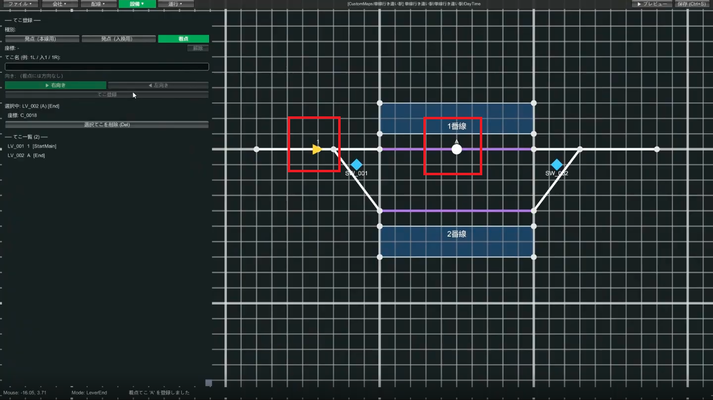
Place the remaining levers (2/B, 11/C, 12/D) the same way. When done, check in Preview.
3-3. Register the routes
Once the levers are placed, routes are easy. In Equipment → Route,
- Click the start lever → click the end lever (e.g. 1 → A for route
1A) - Click the track circuits it passes through in order (e.g. the straight side of the switch → Track 1's track circuit)
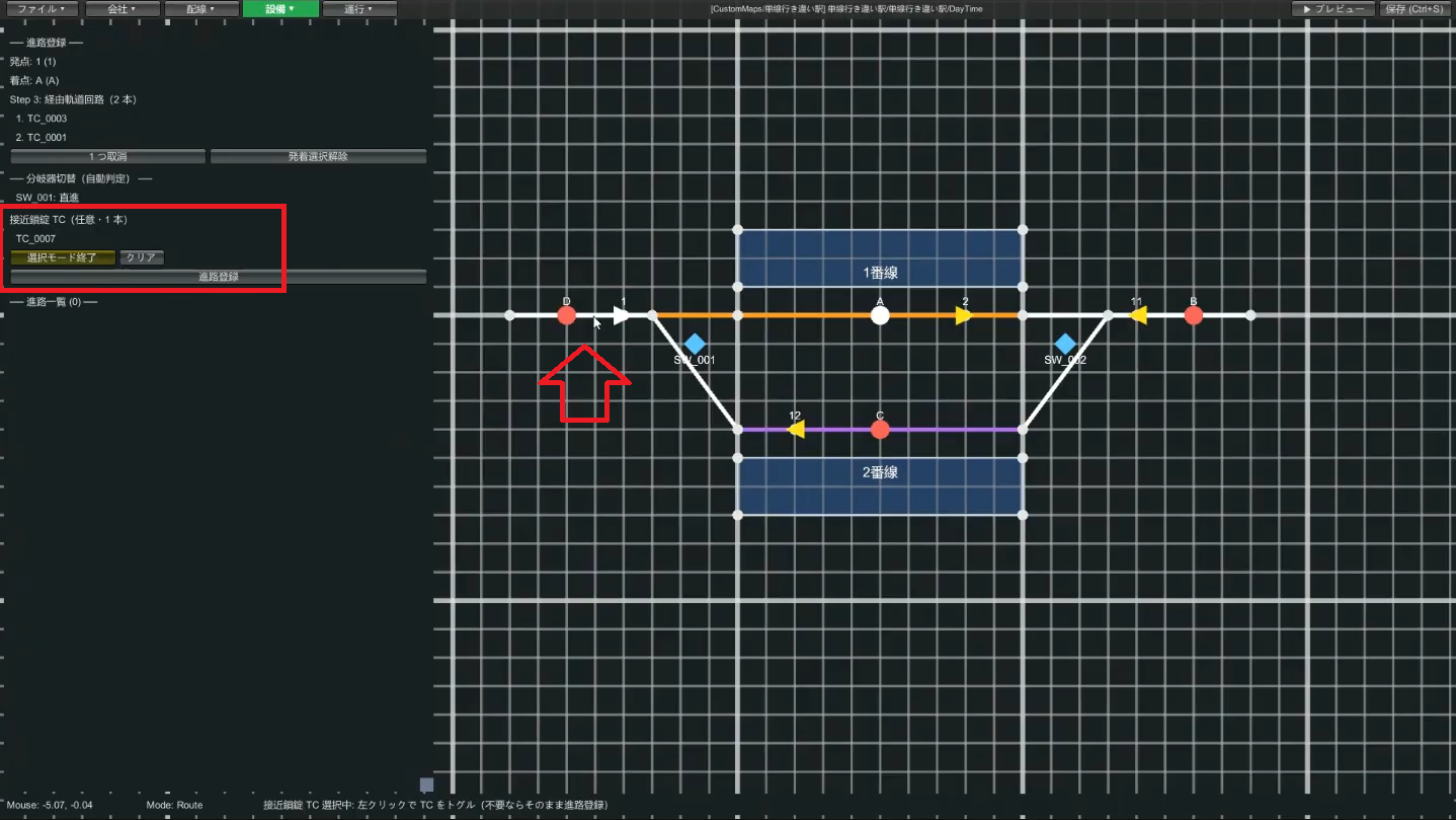
- (Optional / advanced) Specify the approach locking track circuit (next item)
- Register. The route name is auto-generated from start + end (e.g.
1A)
The track circuits you chain together form the area that the route's signal (home / starting / shunting) protects. While any of those track circuits is occupied, the signal stays red, blocking further trains from entering.
Therefore, do not include the track circuit where the start lever or the signal itself is placed. If you do, the moment the train reaches that lever/signal position, the signal protects its own location, turns red, and the train stops right there.
When wiring, decide which track circuit "handles" the signal, place the lever and signal on the near side of that boundary, and let the route's chained circuits begin on the far side.
Example: if the layout is TC_A → TC_B → TC_C with the start lever on TC_A, the home signal at the TC_A/TC_B boundary, and the end lever on TC_C, the route should chain TC_B and TC_C. TC_A is excluded. The end lever's track circuit TC_C is included (the end lever marks where the route terminates, and its track circuit sits inside the route's protected range).
TC_A (excluded), the home signal at the TC_A/TC_B boundary, and the end lever on TC_C. The route chains TC_B through TC_C.3-4. (Optional / advanced) Set up approach locking
If you select an "approach locking track circuit" when registering a route, then while a train is on that track circuit, the route can't be released on its own. Normally you specify the track circuit (right in front of the signal) where the start lever is. For details, also see the Glossary "approach locking".
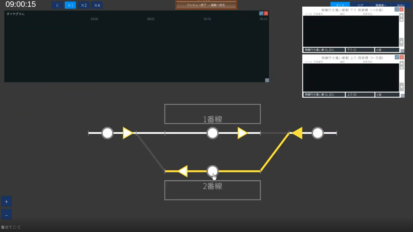
Once you've registered the four routes (1A, 2B, 11C, 12D) the same way, operate the levers in Preview and confirm that the switches actually change over.
3-5. Place the signals
Equipment → Signal. A signal goes together with a route—one signal per route. The side where a train arrives is the home signal, and the side it departs from is the starting signal (the mechanism is the same).
- In signal mode, choose the type (home / starting) and click a coordinate on the map
- Click the start lever and end lever to specify the route it serves (e.g. 1 → A for the
1Asignal) - Register signal
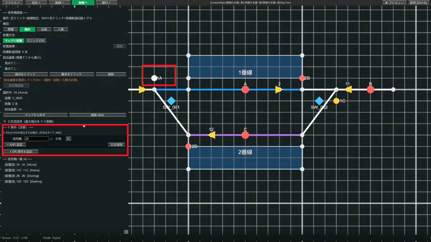
Place one for each of the four routes (home: 1A, 11C; starting: 2B, 12D).
3-6. (Optional / advanced) Enable yellow aspects
Click a signal to enter edit mode, then "Add OR condition" → specify the next signal (e.g. beyond 1A is 2B) being red and save. Now if the next is red the one before shows yellow, and if the one beyond that is green the one before is green too—a realistic three-aspect display.
3-7. Place the departure buttons
- Equipment → Departure Button. Click a coordinate to place it
- Choose the station it serves and the departure sound (bell / buzzer), then Register button
- Place one on both Track 1 and Track 2, and the equipment is complete
→ For more, see the Equipment editing guide
📋 STEP 4 Operations (build the diagram)
The Operations category is only available when a scenario is selected. Proceed in order: Path Group → Train → Diagram.
4-1. Create a path group
A path group is a "template for the path a train travels". Writing out each train one by one is a lot of work, so you group routes together and reuse them. First, create the group for right-bound (into and out of Track 1).
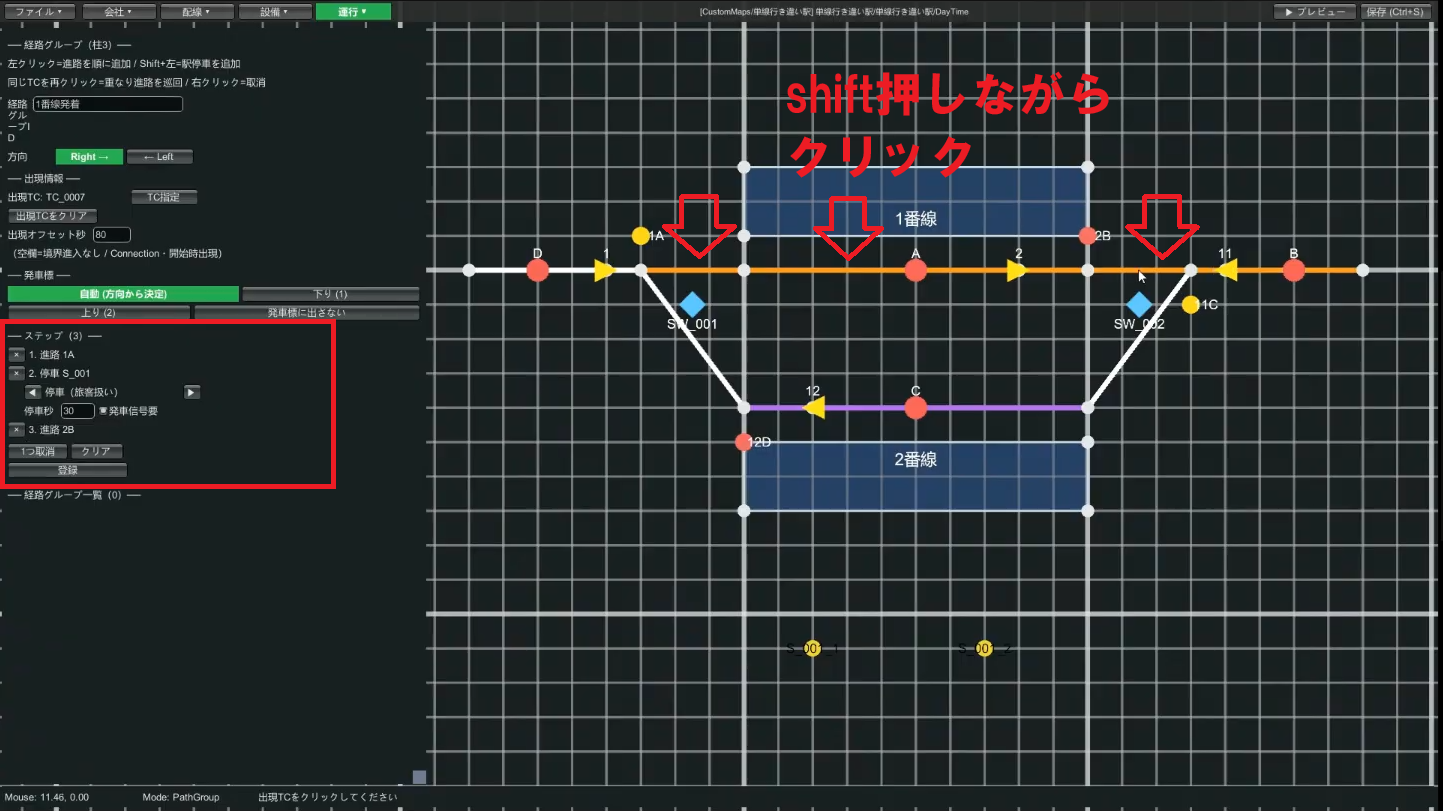
- Operations → Path Group. Enter a path group ID (e.g.
Track 1 arrival) - Choose the direction (right / left). Right-bound, so "right"
- Choose the appearance TC = the track circuit where the train appears (the left-end single-track TC). The appearance offset is how many seconds before the station stop it appears (e.g. 80 seconds)
- The station direction can be left at "Auto (determined from direction)"
- Register the steps in order: left-click the track circuit of route
1A→ Shift+left-click the Track 1 track circuit where it stops (station stop) → left-click the track circuit of the departure route2B - Once the three steps are registered, click Register
Create the left-bound (Track 2) group the same way (ID e.g. Track 2 departure, direction "left", appearance TC is the right-end single-track TC, steps are 11C → stop at Track 2 → 12D).
4-2. Register the trains
In Operations → Train List, register the trains to run. Since they pass each other, create two.
| Item | Train 1 | Train 2 |
|---|---|---|
| Train number | 1001 | 1002 |
| Train type | Series 1 | Series 1 |
| Train class | Local | Local |
| Path group | Track 1 arrival (right-bound) | Track 2 departure (left-bound) |
| Arrival time | 10:00 | 10:00 |
| Departure time | 10:01 | 10:01 |
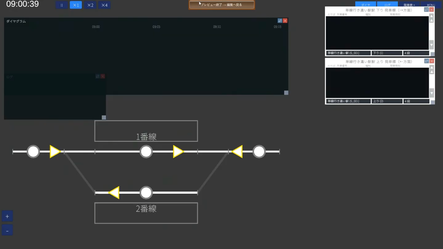
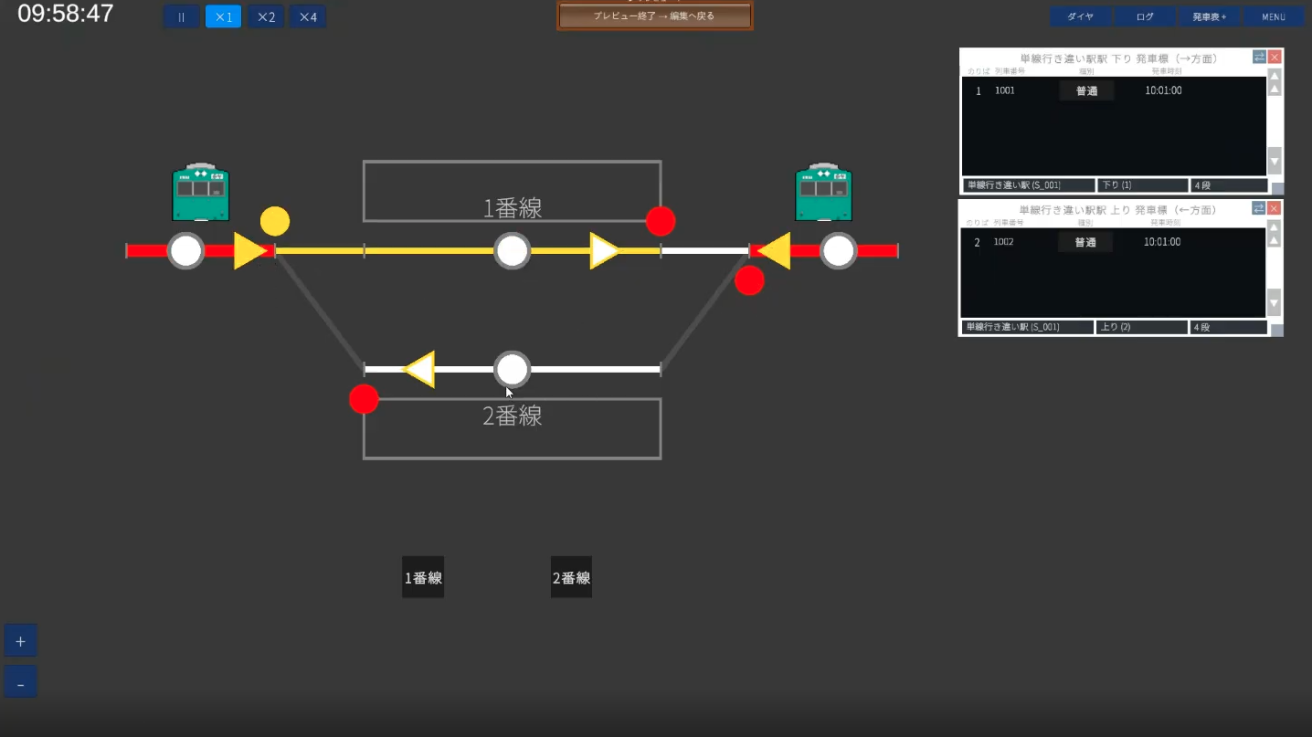
If both arrive and depart at the same time, the two trains pass at the station. Once saved, run ▶ Preview to confirm trains appear on the departure indicator and actually appear and depart (try pressing the departure button too).
4-3. Show the diagram (optional)
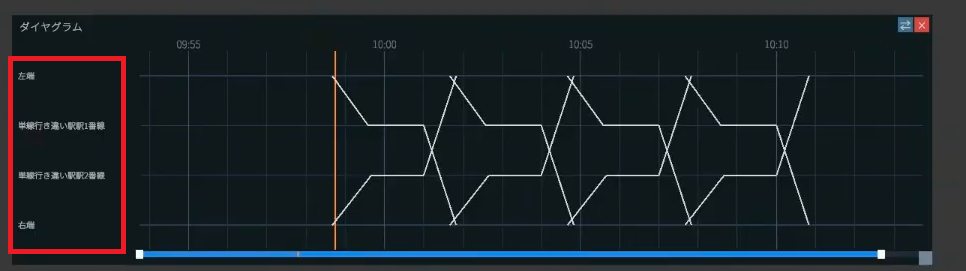
At this point the trains move. The last step is the setup to show the diagram (a time × position graph). Feel free to skip it if it's tricky.
In Operations → Diagram Row, register the rows that line up along the graph's vertical axis, from top to bottom.
- Left end (map edge): type "Terminal", a display name (e.g.
Left end), and select the corresponding track circuit - Station Track 1 / Track 2: type "Platform", select the station and track number, and register
- Right end (map edge): same as the left end
Lining them up as Left end → Track 1 → Track 2 → Right end—the edges first and last, the station's tracks in the middle—draws the diagram.
4-4. Add more trains (copy)
Once you have one, you can mass-produce similar trains with Copy in Operations → Train List. Just change the train number and times.
→ For more, see the Operations editing guide
🎉 Done! On to the next level
Nice work. You've now gone full circle through the basics of a custom map: two trains passing each other on a single track. If you've got a feel for the Company → Wiring → Equipment → Operations flow and the relationship between levers, routes, and signals, that's a big success.
If it doesn't work
- Read the messages when saving: warnings like "the route doesn't reference a track circuit" are telling you what setup is missing
- Preview often: checking one or two trains at a time lets you immediately catch a wrong appearance-TC direction or a mistake in step order
- Can't place a lever: that's a sign the track circuit is too short. Redraw it longer (3–5 cells)
- Trains back up: check that the spacing on the single track isn't too close
Related guides
- Your first custom map — a recap of the concepts
- Company / Wiring / Equipment / Operations — details on each feature
- Glossary — check terms
- Playing user maps — play your finished map